Pneumatic silencer, compressed air silencer
Where does pneumatic silencer work? – In automated production, equipment is often used that requires compressed air to be moved and controlled. At the end of an operating cycle of such a system, the compressed air is released into the environment. The high speed of the pressurized air creates a loud noise that can affect the well-being, productivity and health of people at work.
In order to reduce the noise level of such pneumatic devices, silencers (air silencers / pneumatic silencers) made of porous materials are used.
A good silencer should not only provide the desired noise level, but also prevent the speed and performance of the equipment from being reduced. Silencers made of porous aluminium meet both requirements. Due to the wide flexibility of the technology, porous aluminum offers the best solution for your noise reduction problems.
Porous aluminum silencers can be used in pneumatic cylinders, valves, air motors, compressors, pneumatic tools and other pneumatic equipment. Silencers not only reduce the noise level of the exhaust air, but also protect the pneumatic system from dust and dirt that could enter through the valve.
Porous aluminium - an innovative material for sound insulation
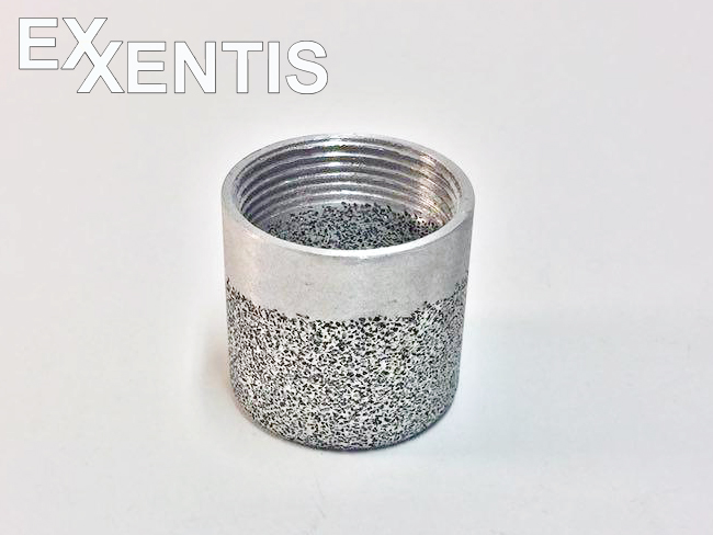
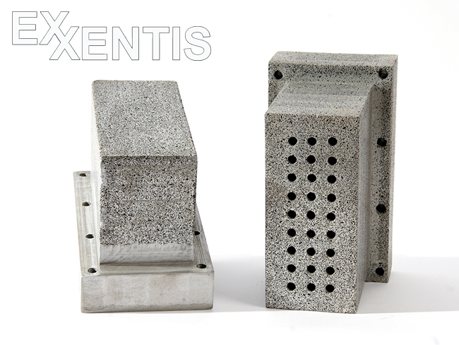
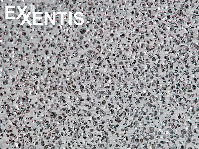
The special feature and advantage of porous aluminium is that it is not produced by sintering individual particles (grains), which can dissolve under the influence of vibrations or shocks, but is cast. This means that the entire porous structure is a single casting and there are no separate particles (grains).
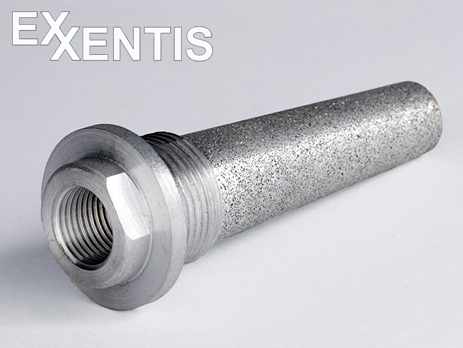
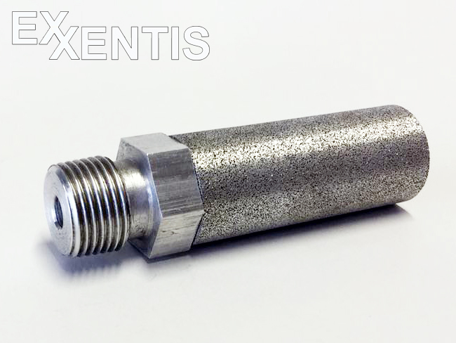
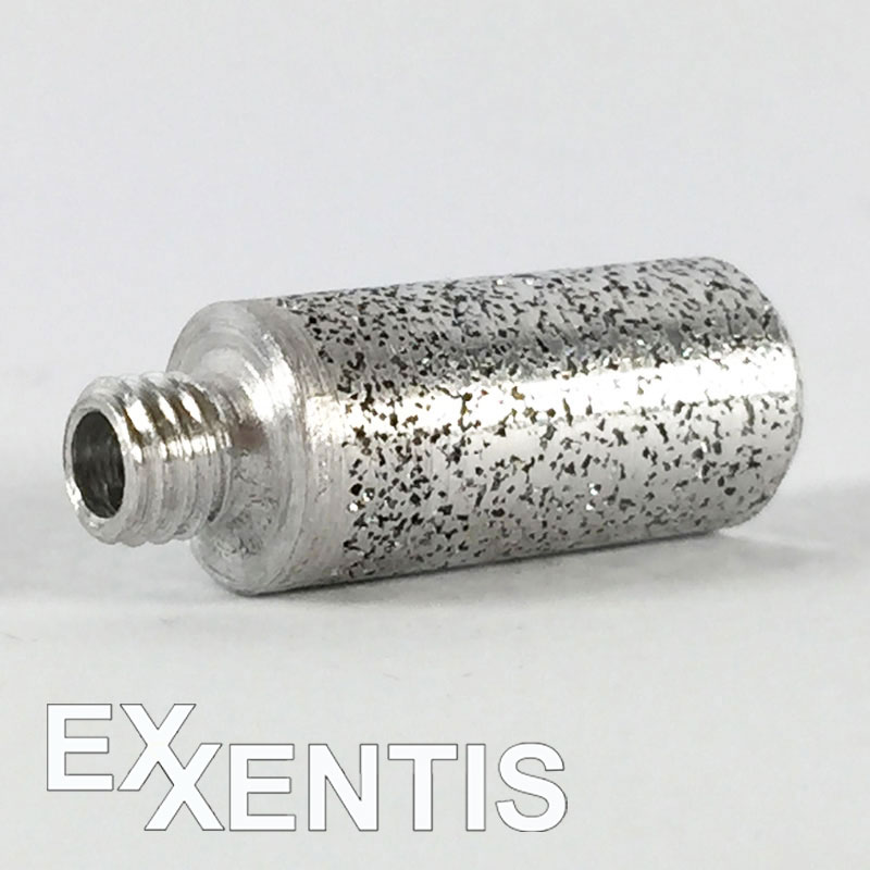
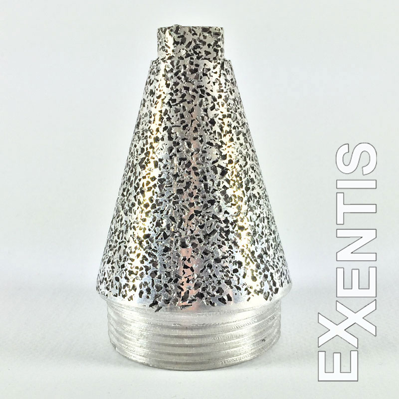
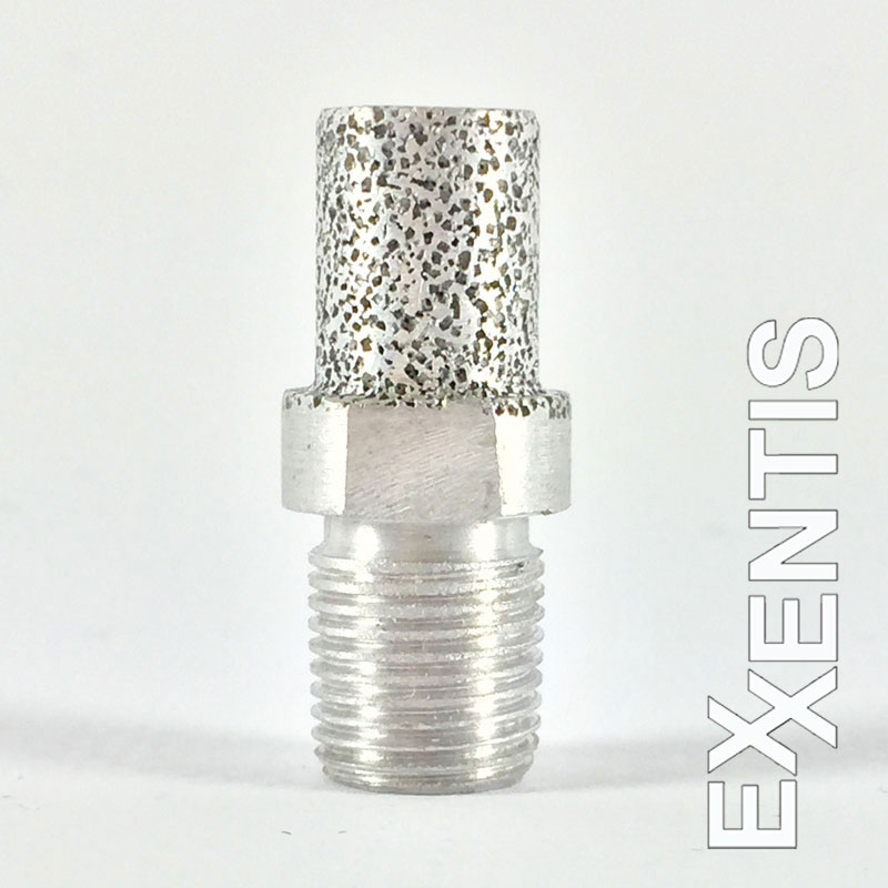
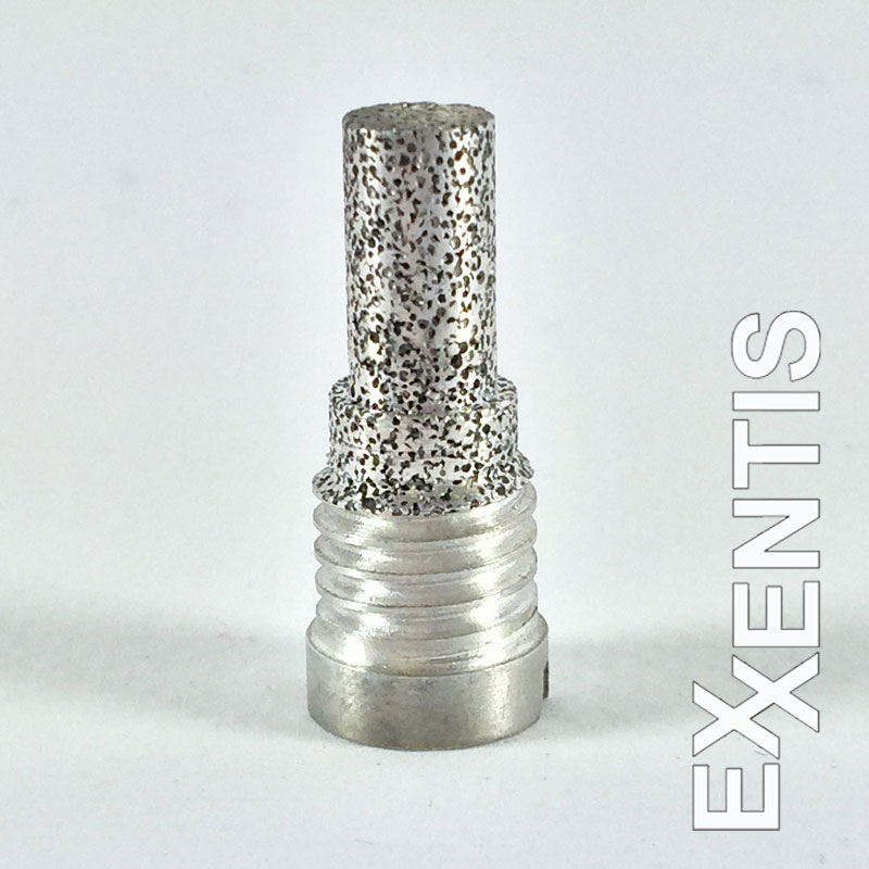
Therefore, the porous cast aluminum is exceptionally resistant to vibration and shock loads. In addition, aluminium is a very ductile, ductile metal. For example, it deforms under shock loads instead of breaking into fragments, as is the case with less ductile metals. Silencers made of porous aluminium are made as a whole piece with porous sections and non-porous sections, i.e. made of solid aluminium for the attachment point.
Dimensions and shape of porous aluminium pneumatic silencers
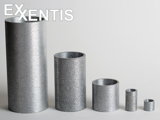
The advantage of porous aluminium is that it is possible to manufacture silencers in almost any shape and size according to your individual requirements. It is also possible to cast the silencer from porous aluminium and the thread from solid aluminium in one piece, which simplifies the whole construction and increases the durability.
Acoustic properties of silencers
Standard pneumatic silencers made of porous aluminium reduce noise by up to 75-85 dB and are installed on the vent valve of compressed air systems.
The sound is attenuated due to a reduction in the air velocity, this happens because:
The air outlet area is increased (the area of a silencer is larger than that of a vent valve).
The exit time is increased (due to the optimally selected hydraulic resistance of the pneumatic silencer).
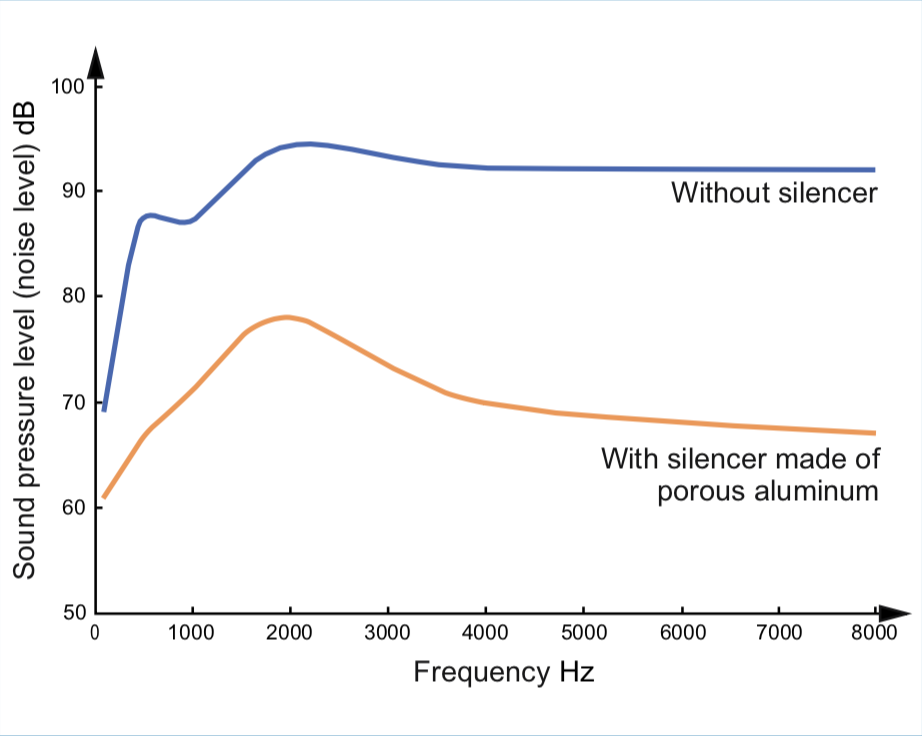
Silencers made of porous aluminium reduce the noise level in the entire frequency spectrum. An example of the noise reduction by a pneumatic silencer made of porous aluminium depending on the sound frequency can be seen in the figure.
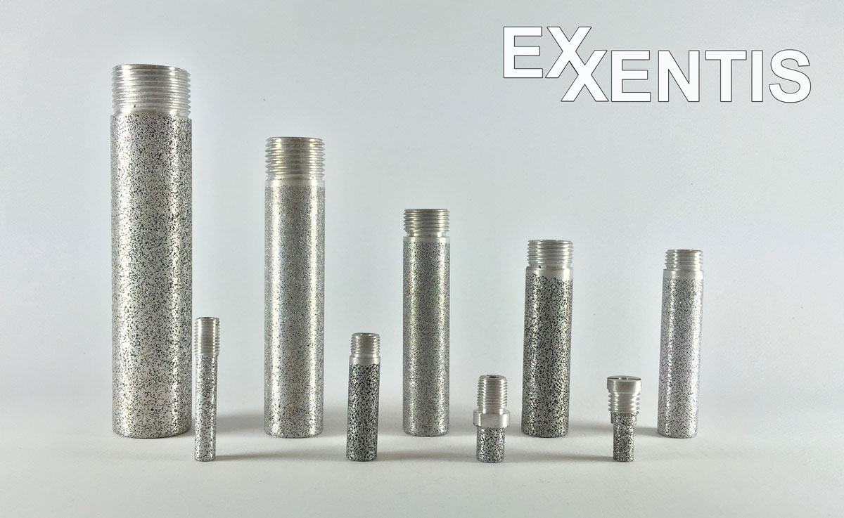
Design and parameters of threaded pneumatic silencers

| Silencer type | R | D mm | d mm | L mm | h mm | SW mm | P max bar | Sound dB | Weight g | kv l/min |
| PST 18-M | G1/8″ | 10 | 4 | 25 | 10 | 10 | 10 | ≤85 | 3 | 15 |
| PST 18-L | G1/8″ | 10 | 4 | 40 | 10 | 10 | 10 | ≤82 | 5 | 24 |
| PST 14-M | G1/4″ | 14 | 8 | 30 | 12 | 14 | 10 | ≤85 | 6 | 28 |
| PST 14-L | G1/4″ | 14 | 8 | 37 | 12 | 14 | 10 | ≤82 | 10 | 51 |
| PST 38-M | G3/8″ | 17 | 11 | 50 | 15 | 17 | 10 | ≤85 | 12 | 59 |
| PST 38-L | G3/8″ | 17 | 11 | 80 | 15 | 17 | 10 | ≤82 | 18 | 95 |
| PST 12-M | G1/2″ | 23 | 13 | 60 | 15 | 24 | 10 | ≤85 | 23 | 65 |
| PST 12-L | G1/2″ | 23 | 13 | 90 | 15 | 24 | 10 | ≤82 | 35 | 108 |
| PST 34-M | G3/4″ | 34 | 24 | 65 | 15 | – | 10 | ≤85 | 33 | 95 |
| PST 34-L | G3/4″ | 34 | 24 | 137 | 15 | – | 10 | ≤82 | 59 | 182 |
| PST 1-M | G1″ | 42 | 30 | 70 | 20 | – | 10 | ≤85 | 47 | 133 |
| PST 1-L | G1″ | 42 | 30 | 169 | 20 | – | 10 | ≤82 | 92 | 285 |
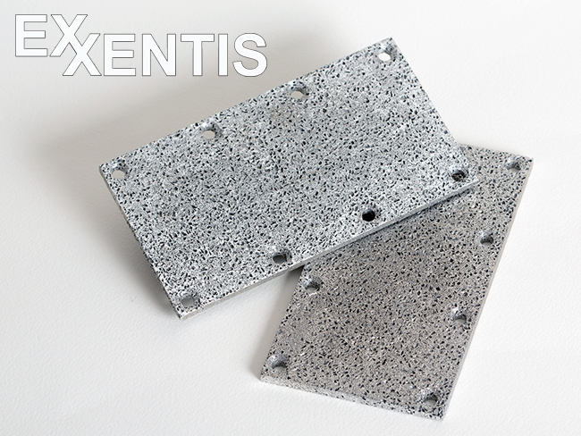
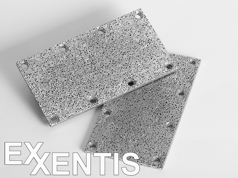
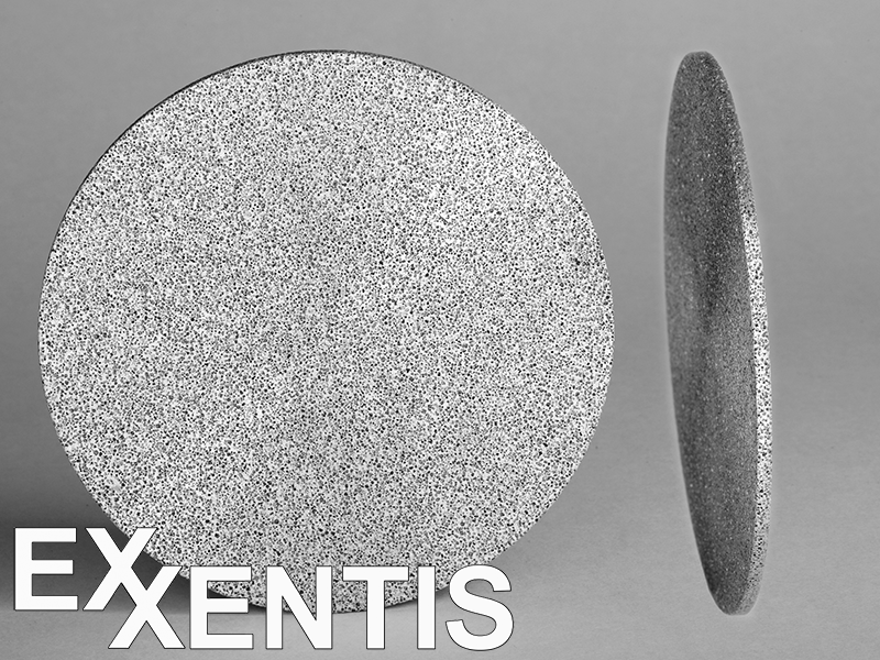
Construction and parameters of flat silencers (in the form of plates and discs)
Porous aluminium enables the production of silencers in the form of discs with rectangular, square and complex plate shapes:
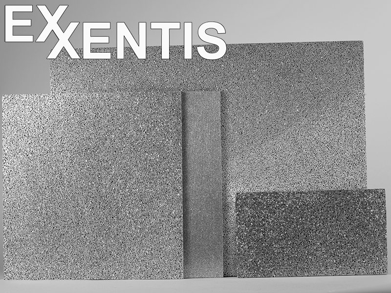
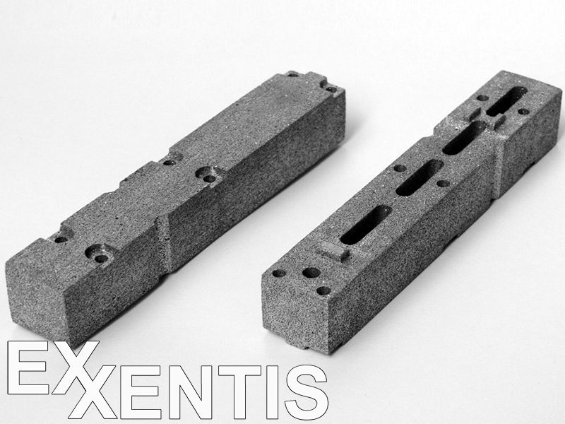
Flat silencers are manufactured according to your requirements. Approximate limits for flat silencers: rectangular or round, as well as any complex shape. Please contact us if you require larger dimensions.
Silencer flow rate
All pores of porous aluminium are open, the material is permeable over the entire volume. The manufacturing process of porous aluminium makes it possible to regulate the flow rate of silencers over a wide range. This results in a low back pressure (pneumatic resistance) of the silencers and a minimal impact on the operation of the pneumatic system.
The flow rate is determined by the Darcy equation:
Q = (К×ΔP×S)/(µ×H)
where Q is the flow rate of air, m3/s; K is the permeability coefficient, m2; ΔP – pressure drop, Pa; S – area of the porous part of the silencer, m2; μ is the viscosity of air, Pa × s; H – wall thickness of the silencer, m.
Permeability coefficient K (m2) for porous aluminium with different pore sizes:
| Nr.1 | Nr.2 | Nr.3 | Nr.4 | Nr.5 | Nr.6 | Nr.7 | |
| Pore size mm | 0.20 – 0.35 | 0.30 – 0.50 | 0.40 – 0.63 | 0.40 – 1.00 | 0.63 – 1.60 | 0.63 – 3.00 | 0.63 – 4.00 |
| Permeability coefficient m2 | 7.00E-12 | 8.50E-12 | 3.10E-11 | 7.50E-11 | 1.45E-10 | 2.25E-10 | 2.60E-10 |
The calculated specific flow rate of porous aluminium for different pore sizes and material thicknesses (compressed air):

Possibilities to increase the flow rate
If necessary, you can increase the flow rate of silencers in one of the following ways:
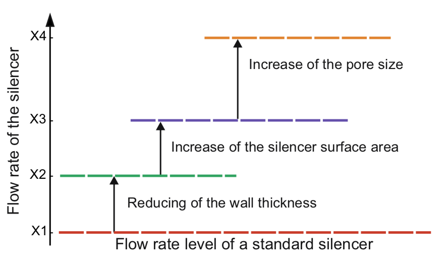
Restrictions:
- The reduction of the wall thickness leads to a slight increase in the noise level and is limited by the requirements for the durability of the silencer.
- An enlargement of the pores can lead to an increased noise level.
All these methods can be used together or separately.
Calculation and selection of a silencer
Calculation of the required area of the silencer
For the standard pore sizes and for compressed air is the formula to calculate the silencer range:
S = 973684×Q×H/ΔP
where S is the area of the porous part of the silencer, m2; Q – volume flow of air, m3 / sec; ΔP – pressure drop (overpressure in the system), Pa; H – wall thickness of the silencer, m (values of 0.003 m or 0.004 m are assumed for standard silencers).
Once you have calculated the required area, you can determine the appropriate type of silencer according to the table:
Area of the porous part of standard porous aluminium silencers
| Silencer type | Thread | Flat of the working part of the silencer m2 | Wall thickness of the silencer m |
| PST 18-M | G1/8″ | 0.000550 | 0.003 |
| PST 18-L | G1/8″ | 0.000879 | 0.003 |
| PST 14-M | G1/4″ | 0.001036 | 0.003 |
| PST 14-L | G1/4″ | 0.001900 | 0.003 |
| PST 38-M | G3/8″ | 0.002198 | 0.003 |
| PST 38-L | G3/8″ | 0.003518 | 0.003 |
| PST 12-M | G1/2″ | 0.003203 | 0.004 |
| PST 12-L | G1/2″ | 0.005340 | 0.004 |
| PST 34-M | G3/4″ | 0.004695 | 0.004 |
| PST 34-L | G3/4″ | 0.009031 | 0.004 |
| PST 1-M | G1″ | 0.006595 | 0.004 |
| PST 1-L | G1″ | 0.014135 | 0.004 |
Determination of silencer type according to flow diagrams
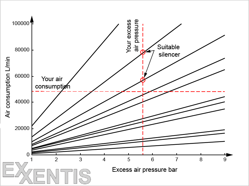
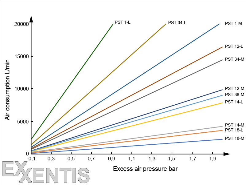
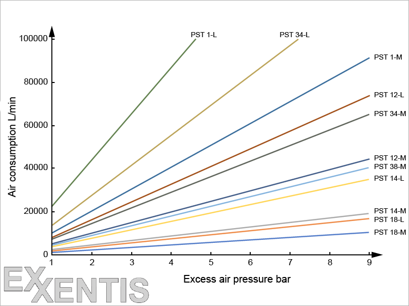
Silencer selection according to table
Maximum consumption table for standard silencers with a pressure difference of 6 bar:
| Air flow l/min | PST 18-M | PST 18-L | PST 14-M | PST 14-L | PST 38-M | PST 38-L | PST 12-M | PST 12-L | PST 34-M | PST 34-L | PST 1-M | PST 1-L |
| <6770 | + | + | + | + | + | + | + | + | + | + | + | + |
| 6770…10840 | + | + | + | + | + | + | + | + | + | + | + | |
| 10840…12770 | + | + | + | + | + | + | + | + | + | + | ||
| 12770…23420 | + | + | + | + | + | + | + | + | + | |||
| 23420…27090 | + | + | + | + | + | + | + | + | ||||
| 27090…29610 | + | + | + | + | + | + | + | |||||
| 29610…43350 | + | + | + | + | + | + | ||||||
| 43350…49360 | + | + | + | + | ||||||||
| 49360…60960 | + | + | + | |||||||||
| 60960…83470 | + | + | ||||||||||
| 83470…130650 | + |
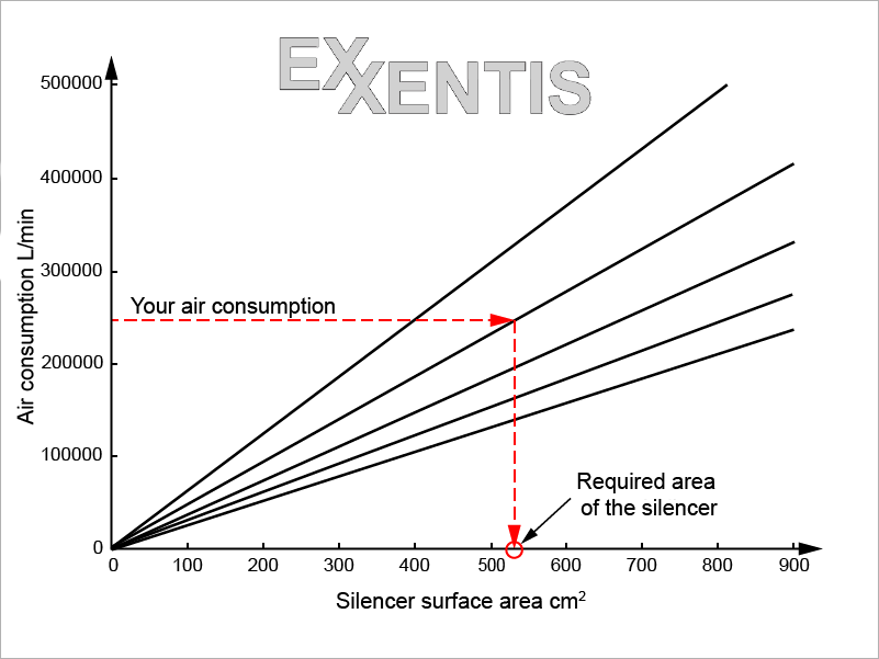
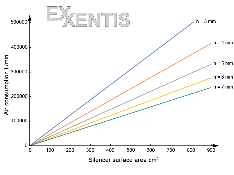
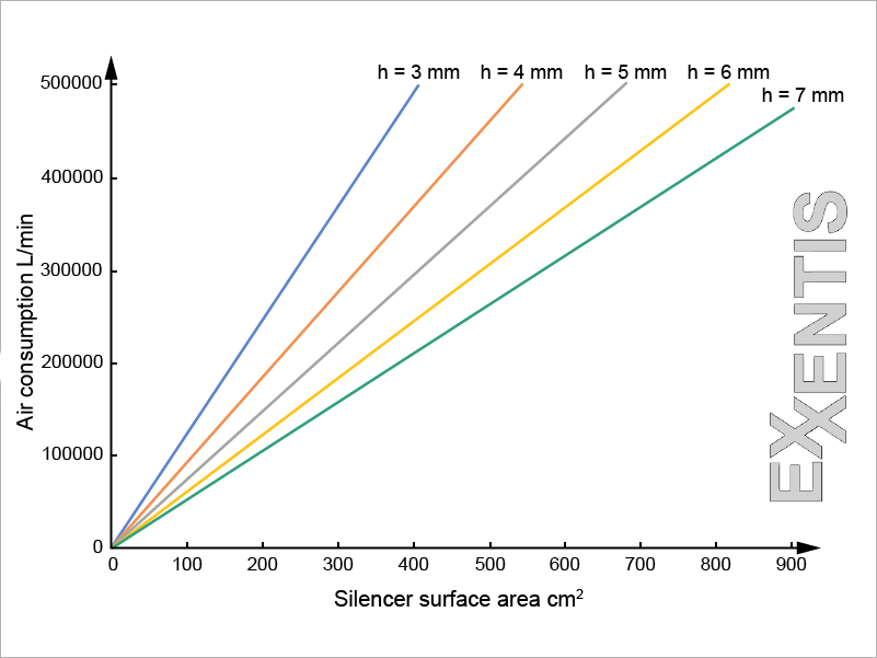
Selection of a flat silencer
For the standard pore sizes and for compressed air is the formula to calculate the silencer range:
S = 973684×Q×H/ΔP
where S is the area of the porous part of the silencer, m2; Q – volume flow of air, m3 / sec; ΔP – pressure drop (overpressure in the system), Pa; H – wall thickness of the silencer, m (values of 0.003 m or 0.004 m are assumed for standard silencers).
The required area of the flat silencer can also be determined from the following graphs depending on the required air flow and the thickness of the silencer. The following diagrams apply to silencers with standard pore sizes. For information on other pore sizes, please send us an inquiry.
Porous aluminium offers an incredible range of possibilities for the manufacture of pneumatic silencers.
We hope you have found all the information you need on our website.
If you still have any questions, please send us an inquiry. We look forward to helping you.